Power and energy
What you will find in this section:
Flow direction of active power/energy
With a positive current, active power (and also active energy) is positive and demanded by a measuring object; with a negative current, active power (and also active energy) is negative and delivered from the measuring object. However, the current displayed by EMpro is always displayed without a sign. The polarity of the current only affects the active power (and also active energy).
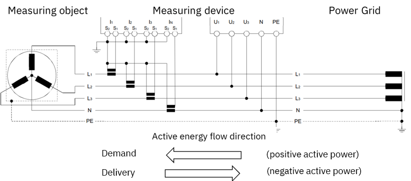
Flow direction of reactive power/energy
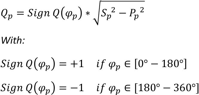
If the phase angle φ between voltage and current takes values between 0° and 180° the reactive power (and also reactive energy) is positive and demanded/consumed by a measuring object. Otherwise reactive power (and also reactive energy) is negative and delivered.
Whether the reactive energy is seen as inductive or capacitive depends on the chosen display setting (according to IEEE or IEC). This setting can be changed via display and web server.

Active power
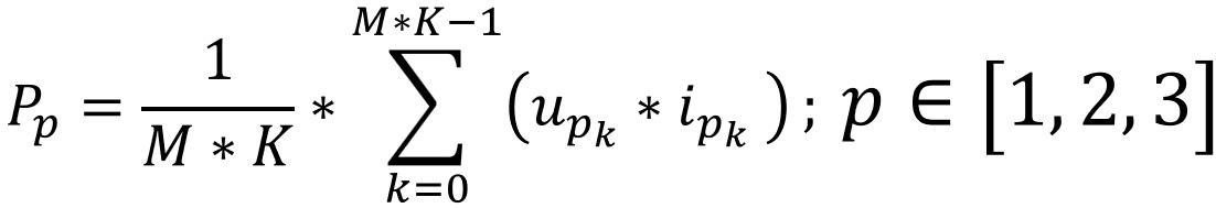
Active power per phase
The system determines the active power of the connected grid.
The method described in the DIN EN 61557-12 standard is used.
M = Number of periods 10 or 12
K = Number of measurements per period, voltages & currents are recorded with K = 256 measurements per period
k = Summation index, p = Considered phase
|
Active power |
 |
Total active power
The total active power is the sum of the active powers of all line conductors.
|
Total active power |
Active energy
The active energy corresponds to the time integral of the active power. Positive active power values are summed up to an active energy demand. Negative active power values are summed up to an active energy delivery.
Reactive power
Reactive power per phase
The reactive power is calculated both from the fundamental wave (Q1,p = displacement reactive power) and including the distortion reactive power (Qp).
The standard DIN EN 61557-12 describes the basic procedure and provides the following formulas for calculation:
p = Considered phase
|
Reactive power |
 |
| Displacement reactive power |
The displacement reactive power is shown in the WBM and on the display.
Total reactive power
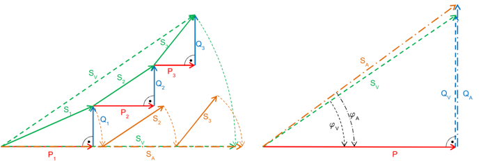
The total reactive power is calculated both vectorially and arithmetically.
|
Total reactive power (vectorial) |
|
|
Total reactive power (arithmetic) |
 formula.jpg) |
The total reactive power shown in the WBM and display is calculated vectorially.
Reactive energy
The reactive energy corresponds to the time integral of the reactive power. Positive reactive power values are summed up to an reactive energy demand. Negative reactive power values are summed up to an reactive energy delivery.
Apparent power
The system determines the apparent power of the connected grid.
The method described in the DIN EN 61557-12 standard is used.
p = Considered phase
|
Apparent power |
Total apparent power
The total apparent power is calculated both vectorially and arithmetically.
|
Total reactive power (vectorial) |
_1.png) |
|
Total reactive power (arithmetic) |
The total apparent power shown in the WBM and display is calculated vectorially.
Apparent power
The apparent energy corresponds to the time integral of the apparent power.
Accuracy of the power/energy values
The accuracy of the power and energy values is specified under Specifications according to IEC 61557-12. This specification only refers to the power measuring device (PMD).
To calculate the accuracy of an entire system the error of the current sensors (and if necessary, the error of voltage sensors) must be added. For this purpose a formula is defined by the standard EN 61557-12 to calculate the overall system performance class (OSPC):

NOTE of IEC 61557-12: In a three-phase system, the class of the three sensors is equal to the class of one sensor provided that the three sensors have the same class. The class of the sensors refers to the classes defined in IEC 61869-2, IEC 61869-3, IEC 60044-7 and IEC 60044-8. When transducers replace sensors, class sensor refers to intrinsic uncertainty of the transducer.
The OSPC is rounded up to the closest standard default value
| 0,2 | 0,3 | 0,5 | 0,75 | 1 | 1,5 | 2 | 2,5 | 3 | 5 | 7,5 | 10 | 15 | 20 |
Example for OSPC of function „total real power“ for EEM-MA370 (0.5 function-related accuracy class) with current sensors (of sensor class 0.5) and voltage transducers (of sensor class 0.5):

Related topics