Wake up configuration
The following wake up reasons can be configured via PAR_WakeUpSourcesCCL:
| PAR_WakeUpSourcesCCL | wake up | stay awake | hint |
| WU_IN | rising edge on WU_IN | WU_IN is supplied | normally CL15 or digital output from VCU |
| VCU_CAN | communication on VCU_CAN | communication on VCU_CAN | |
| CHARGING_CAN | communication on CHARGING_CAN | communication on CHARGING_CAN | |
| Plug_Connected | rising edge of CP and steady Voltage >2V | CP Signal is detected with duty cycle 1 ..100% | AC- charger will keep current duty cycle and won't switch to 100% like DC in high level communication Only PseudoSleep possible |
| Plug_Released | falling edge of CP and steady <2V | CP Signal in not detected (unplugged) or with duty cycle 0% | AC- charger will keep current duty cycle and won't switch to 100% like DC in high level communication Only PseudoSleep possible does not make sense without Plug_Connected (CHARX EVC-100 will never go to sleep) |
| Plug_Connected AND Plug_Released | wakes up on rising and falling edge of CP | stays awake for at least PAR_WakeUpSleepTime | AC- charger will keep current duty cycle and won't switch to 100% like DC in high level communication Only PseudoSleep possible |
| no Resource configured | supply on C30 | power supply on CL30 | intention is to keep CHARX EVC-100 awake for integration purposes |
CHARX EVC-100 will go to sleep after PAR_WakeUpSleepTime if all of the following applies:
- all configured wake up reasons are not present
- CHARX EVC-100 is prior charging cycle and Lock is not closed
- CHARX EVC-100 is post charging cycle
Please note, if CHARX EVC-100 goes to sleep with locked plug, CHARX EVC-100 needs to be woken up first to release the lock
AC Pseudo Sleep
To let the vehicle sleep even while AC-Charger is connected a pseudo sleep is implemented. The goal of the feature is to lower the current consumption of the vehicle at over night charging if vehicle won't charge any more.
To prevent wake up of the vehicle, external communication is shut off and all not need peripherals are powered down.
Entry conditions for pseudo sleep
- no current AC charging session and first ac charging session has ended (VCU_ChargeParmission = FALSE)
- Lock is open OR Lock is closed and Button is configured
- no configured WakeUpSource instead of Plug_Connected / Plug_Released is active
- PAR_WakeUpSleepTime elapsed
Pseudo sleep behavior
In pseudo sleep CHARX EVC-100 will:
- disable CAN communication
- disable SensorSupply
- disable HMISupply
- disable internal not needed peripherals
If lock is closed and button is pressed lock will be released.
Exit conditions for pseudo sleep
If plug is removed CHARX EVC-100 will went to sleep.
If a configured wake up source becomes true (instead of Plug_Connected / Plug_Released) CHARX EVC-100 will reboot and comes up with a correct initialized system.
Exit condition for pseudo sleep
known issue Pseudo sleep Currently (Version V01.06.xx) if debug messages are enabled (PAR_CANEnableDebugMessages = TRUE) these messages will be forwarded even in pseudo sleep. This behavior is unwanted. Quick solution set PAR_CANEnableDebugMessages = FALSE (should be normal in field)
Interlock setup
The CHARX EVC-100 provides two independent interlock measurements these interlocks can be enabled via parameter PAR_FuncHVInterlockVariant:
Both Interlocks are measured independent and if the resistor is less than 50 Ohm the interlock is detected as closed.
If an interlock is enabled and not detected as closed and the switches are closed, the CHARX EVC-100 will open the switches immediately.
| PAR_FuncHVInterlockVariant | |
| NONE | No HV-Interlock observation is enabled. |
| BOTH | both interlock observations are enabled for safety measures. |
| IL_1 | Parameter is used if only interlock 1 is used for safety measure. |
| IL_2 | Parameter is used if only interlock 2 is used for safety measure. |
Possible UseCase for customer:
- IL_1 defines the state of the Inlet_HV_Plug
- IL_2 defines the state of the Vehicle_HV_Plug
The VCU can detect which Plug is correctly equipped and which HV-circuit is open.
LED configuration
LEDs can be controlled by the CHARX EVC-100 itself or by the connected VCU via CAN via parameter PAR_FuncLEDControl
Known issues
B-Sample:
- Due to HW-Limitations on B-Sample the intensity of the LEDs is limited by SW independent of PAR_LEDxCurrent if Supply Voltage is greater than 14 V. If not protected in this way the LEDs will take harm permanently
- Due to HW-Limitations on B-Sample setting of very small currents at 24V for LED leads to a relative measured high deviation of set current.
C-Sample:
- none
Software configuration
Adjust max brightness
The maximal brightness of each LED can be adjusted separately by PAR_LEDxCurrent
Internal control
If PAR_FuncLEDControl is set to INTERNAL the CHARX EVC-100 controls the LED as shown in following table:
| LED Status | Description |
| Yellow continuously on | Inlet lock closed no charging initialization or active charging |
| Green continuously on | Charging initialization on going |
| Green flashing 1Hz | Charging active |
| Red continuously on | An error occurred, charging not possible |
| LED off | Lock open and no error detected |
External control
If LED is under external control, all 4 LEDs can be controlled by the VCU directly by setting the PWM via CAN-Messages VCU_LEDControl.
You can send every 100ms a CAN-Message with a new PWM value for each LED. The following table shows examples of PWM-values for external controlled blinking modes:
| Time[ms] | Steady on [%] | Steady off [%] | Blinking [%] | Fading [%] |
| 100 | 100 | 0 | 100 | 20 |
| 200 | 100 | 0 | 100 | 40 |
| 300 | 100 | 0 | 100 | 60 |
| 400 | 100 | 0 | 100 | 80 |
| 500 | 100 | 0 | 100 | 100 |
| 600 | 100 | 0 | 0 | 80 |
| 700 | 100 | 0 | 0 | 60 |
| 800 | 100 | 0 | 0 | 40 |
| 900 | 100 | 0 | 0 | 20 |
| 1000 | 100 | 0 | 0 | 0 |
Hardware configuration
The CHARX EVC-100 drives the 4 LED channels. The cathode has to be connected to GND.
If an RGB LED is used a common cathode is requested
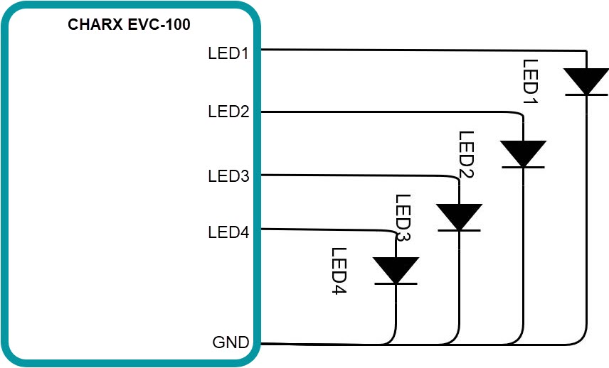
Internal control
If PAR_FuncLEDControl is set to INTERNAL the following connection of RGB LED is requested:
| Channel | Colour |
| LED1 | Red |
| LED2 | Green |
| LED3 | Blue |
| LED4 | - |
External control
No further restrictions.
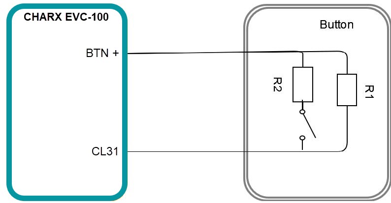
Button configuration
The Button can be used at the Inlet to stop the charging cycle.
If PAR_ShutdownDirectly = TRUE and the Button is pressed, CHARX EVC-100 will end the current charging cycle.
If PAR_ShutdownDirectly = FLASE and the Button is pressed, CHARX EVC-100 will just forward the state of the button and the VCU needs to handle the abort wish of the customer. The actual inaccuracy for Button measurement is defined as:
- for R <= 5.000 Ohm the accuracy is => 100Ohm
- for R > 5000 Ohm, the accuracy is => 500Ohm
Button configuration for NONE
CHARX EVC-100 will always report an SNA for Button to VCU
Button configuration
| Parameter |
Par_FuncButtonSupport = NONE |
Par_FuncButtonSupport = SIMPLE_NO |
Par_FuncButtonSupport = DIAG |
| PAR_ButtonClosedMax | ignored | 0...12kOhm [1] | 0...12kOhm [1] |
| PAR_ButtonClosedMin | ignored | 0...12kOhm [1] | 0...12kOhm [1] |
| PAR_ButtonDiagMax | ignored | ignored | 500...12kOhm |
| PAR_ButtonDiagMin | ignored | ignored | 500...12kOhm |
For the parameter an overlap detection will be executed and leads to an error.
Please ensure a threshold of at least the inaccuracy for these values. To ensure robustness due to external radiation nominal value +- 15% is recommended.
- value needs to be above 500Ohm to be able to detect short to ground.
Hardware configuration
Button configuration example
Diagnostic resistors parallel or in series to the close contact (similar circuit to Lockfeedback(SINGLE_DIAG)). Due to the variants in resistor network (parallel/serial circuit), the parameter describes the measured resistor of the button. In Case of the picture below the following values needs to be calculated:
- Diag = R1
- Closed= R1 || R2