ParameterOverview
|
Title |
Description |
Minimum Value |
Maximum Value |
Unit |
Increment Value |
Default Value |
||||||||||||||||||||||||||||||||||||||||||||||||||
| PAR_ApplIsolationTimeout | This parameter defines the time till the CCL sets an communication error for isolation measurement if no final response from the SECC is received. | 10 | 200 | Second | 1 | 60 | ||||||||||||||||||||||||||||||||||||||||||||||||||
| PAR_ApplWaitForCommunic ation |
This parameter defines the time till the CCL sets an communication error measured from plug detection till inlet locking. Precondition to lock the inlet:
|
10 | 200 | Second | 1 | 60 | ||||||||||||||||||||||||||||||||||||||||||||||||||
| PAR_ApplWaitForHVReady | This parameter defines the time till the CCL sets an communication error measured from closed lock till the EV reports HV ready. | 10 | 600 | Second | 1 | 60 | ||||||||||||||||||||||||||||||||||||||||||||||||||
| PAR_ButtonDiagHigh | Upper limit of diagnostic resistor measured if button is not pressed | 500 | 12000 | Ohm | 1 | 11000 | ||||||||||||||||||||||||||||||||||||||||||||||||||
| PAR_ButtonPressedHigh | Upper limit of resistor measured if button is pressed | 0 | 12000 | Ohm | 1 | 1200 | ||||||||||||||||||||||||||||||||||||||||||||||||||
| PAR_ButtonPressedLow | Lower limit of resistor measured if button is pressed | 0 | 12000 | Ohm | 1 | 800 | ||||||||||||||||||||||||||||||||||||||||||||||||||
| PAR_CAN_CCL_GE | This Parameter describes the group extension of the base address for transmit messages for the different CCLs on a bus together with the HW function coding. | 0 | 240 | - | 1 | 0 | ||||||||||||||||||||||||||||||||||||||||||||||||||
| PAR_CAN_VCU_GE | This Parameter describes the group extension of the base address for receive messages for the different CCLs on a bus together with the HW function coding. | 0 | 240 | - | 1 | 16 | ||||||||||||||||||||||||||||||||||||||||||||||||||
| PAR_CANBitrateCHARGING_ CAN |
Buss speed of Charging Can used during application.
|
- | - | - | - | SNA | ||||||||||||||||||||||||||||||||||||||||||||||||||
| PAR_CANBitrateVCU_CAN |
Buss speed of Charging Can used during application.
|
- | - | - | - | 500kbit/s | ||||||||||||||||||||||||||||||||||||||||||||||||||
| PAR_CANCCLSourceAddress |
This Parameter describes the source address part of the base address for transmit messages for the different CCLs on a bus together with the HW function coding. |
1 | 250 | - | 1 | 130 | ||||||||||||||||||||||||||||||||||||||||||||||||||
| PAR_CANEnableCMS_XCPFo rwarding |
If more than one CCL is equipped to a vehicle XCP forwarding to CMS needs to be enabled or disabled due to the fact, that the CMS has a fixed address for communication. UDS forwarding will be done in dependence of function coding (CMS 2.0 or newer required)
|
- | - | - | - | TRUE | ||||||||||||||||||||||||||||||||||||||||||||||||||
| PAR_CANEnableDebugMess ages |
The parameter describes if CCL debug messages are send out via VCU_CAN:
|
- | - | - | - | FALSE | ||||||||||||||||||||||||||||||||||||||||||||||||||
| PAR_CANIvtCanId |
This Parameter describes where the CAN-IDs of the IVT-S result messages start.
|
1 | 65535 | - | 1 | 1313 | ||||||||||||||||||||||||||||||||||||||||||||||||||
| PAR_CANMonitorE2EProtection |
This parameter enables the E2E protection for message VCU_SafeSignals and CCL_SafePlugStates. If E2E protection is enabled, there must be a valid CRC as well as an incrementing sequence counter. If this is not the case the ECU is going to safe state within 100 ms. For information how to calculate the CRC, please check the user guide.
|
- | - | - | - | FALSE | ||||||||||||||||||||||||||||||||||||||||||||||||||
| PAR_CANTerminationCHARGING_CAN |
The parameter describes if the CHARGING_CAN is not terminated
|
- | - | - | - | FALSE | ||||||||||||||||||||||||||||||||||||||||||||||||||
| PAR_CANTerminationVCU_CAN |
The parameter describes if the VCU_CAN is not terminated
|
- | - | - | - | FALSE | ||||||||||||||||||||||||||||||||||||||||||||||||||
| PAR_CANVCUSourceAddress | This Parameter describes the source address part of the base address for receive messages for the different CCLs on a bus together with the HW function coding. | 0 | 250 | - | 1 | 128 | ||||||||||||||||||||||||||||||||||||||||||||||||||
| PAR_ChargingCurrentSource |
This Value describes the source of the charging current measurement
|
- | - | - | - | EVSE | ||||||||||||||||||||||||||||||||||||||||||||||||||
| PAR_DCThresholdVoltage | This value defines the maximum voltage difference between inlet and vehicle voltage in which the switches are allowed to be closed. ISO 61851 defines 20 Volt | 5 | 40 | Volt | 0,1 | 20 | ||||||||||||||||||||||||||||||||||||||||||||||||||
| PAR_DisconnectInletVoltage | during disconnection of the HV connection the charging voltage needs to be below a limit to prevent a flash 60V in accordance to ISO61851 |
0 | 100 | Volt | 0,1 | 60 | ||||||||||||||||||||||||||||||||||||||||||||||||||
| PAR_FuncButtonSupport |
Defines the type of Button used:
|
- | - | - | - | NONE | ||||||||||||||||||||||||||||||||||||||||||||||||||
| PAR_FuncCCCheckLow |
Enumeration if function observe reverse charging current enabled or not
|
- | - | - | - | FALSE | ||||||||||||||||||||||||||||||||||||||||||||||||||
| PAR_FuncHVInterlockVariant |
The parameter describes the usage of the HV interlock connection.
|
- | - | - | - | NONE | ||||||||||||||||||||||||||||||||||||||||||||||||||
| PAR_FuncLEDControl |
Enumeration to show if the HMI LEDs are handled by the CCL or by an external source ( e.g. VCU)
|
- | - | - | - | INTERNAL | ||||||||||||||||||||||||||||||||||||||||||||||||||
| PAR_FuncObserveCPCommunication |
If the Vehicle does not support prevent drive off during charging based on Plug state the CP communication could be optional used to detect a broken cable. Enumeration if function observe CP communication as safety function to detect a broken cable is enabled or not
|
- | - | - | - | FALSE | ||||||||||||||||||||||||||||||||||||||||||||||||||
| PAR_HVSWCharacteristics |
This parameter describes the characteristic of the analogue connected HVSWs:
Note: with additional environment conditions an active economizer can influence the open load detection during start up by detecting an open load even if the switch is connected. For active economizer open load will be detected the first time while closing the switch. |
- | - | - | - | SIMPLE | ||||||||||||||||||||||||||||||||||||||||||||||||||
| PAR_HVSWDelayBetweenClo sing | This parameter describes the delay between the two switches to be closed. | 0 | 100 | ms | 10 | 0 | ||||||||||||||||||||||||||||||||||||||||||||||||||
| PAR_HVSWSink |
This Value describes the sink of the HVSW
|
- | - | - | - | ANALOG | ||||||||||||||||||||||||||||||||||||||||||||||||||
| PAR_HVSWTimeClosing | This parameter describes the time till the switch is closed and diagnostics starts again to avoid miss measurement due to bouncing effects. This Parameter depends on the chosen switch and should be as less as possible. | 0 | 1000 | ms | 10 | 200 | ||||||||||||||||||||||||||||||||||||||||||||||||||
| PAR_HVSWTimeReleasing | This parameter describes the time till the switch is opened and diagnostics starts again to avoid miss measurement due to bouncing effects. This Parameter depends on the chosen switch and should be as less as possible. | 10 | 1000 | ms | 10 | 50 | ||||||||||||||||||||||||||||||||||||||||||||||||||
| PAR_InletType |
This Parameter defines the used Inlet of the vehicle.
|
- | - | - | - | CCS2 | ||||||||||||||||||||||||||||||||||||||||||||||||||
| PAR_InletVoltageSource |
This Value describes the source of the inlet voltage measurement
|
- | - | - | - | EVSE | ||||||||||||||||||||||||||||||||||||||||||||||||||
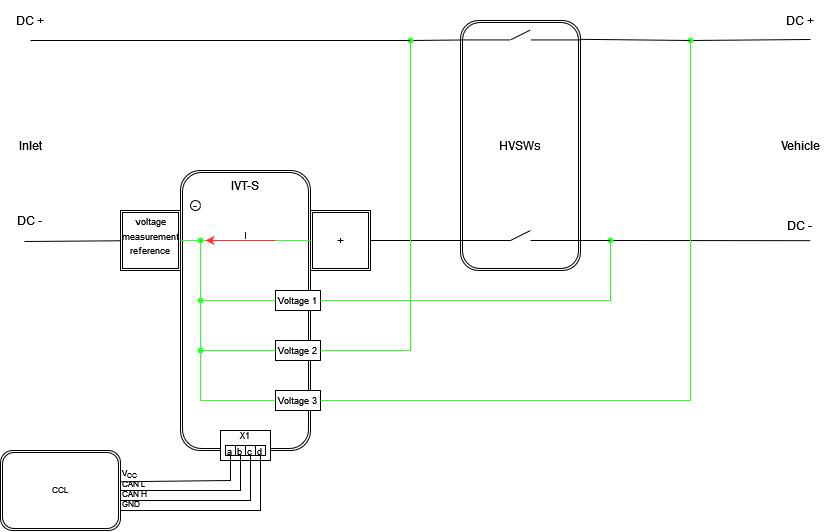
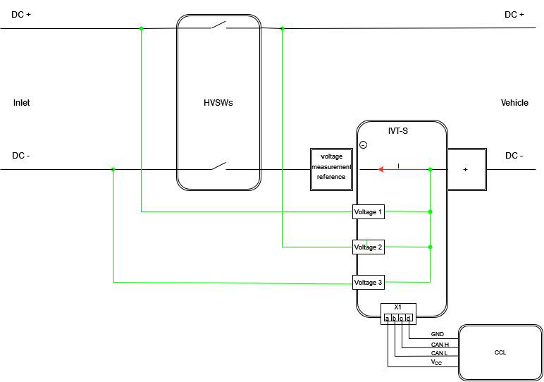
| PAR_IvtWiring |
This parameter alocates the IVT in the DC+/DC- path if one of the following parameters is configured to IVT_CHARGING_CAN || IVT_VCU_CAN, :
PAR_IVTWiring = INLET.
PAR_IVTWiring = VEHICLE.
|
|||||||||||||||||||||||||||||||||||||||||||||||||||||||
| PAR_LED1Current | To adopt the brightness of the LED to the used hardware the constant current for the LED supply is adjustable. | 20 | 100 | mA | 5 | 20 | ||||||||||||||||||||||||||||||||||||||||||||||||||
| PAR_LED3Current | To adopt the brightness of the LED to the used hardware the constant current for the LED supply is adjustable. | 20 | 100 | mA | 5 | 20 | ||||||||||||||||||||||||||||||||||||||||||||||||||
| PAR_LED4Current | To adopt the brightness of the LED to the used hardware the constant current for the LED supply is adjustable. | 20 | 100 | mA | 5 | 20 | ||||||||||||||||||||||||||||||||||||||||||||||||||
| PAR_LockFeedback |
Lock feedback is done in two different ways. the CCL supports
|
- | - | - | - | SINGLE_ DIAG | ||||||||||||||||||||||||||||||||||||||||||||||||||
| PAR_LockFeedbackClosedM ax | Maximum resistor value for lock close detection. | 0 | 12000 | Ohm | 50 | 10500 | ||||||||||||||||||||||||||||||||||||||||||||||||||
| PAR_LockFeedbackClosedMi n | Minimum resistor value for lock close detection. | 0 | 12000 | Ohm | 50 | 9500 | ||||||||||||||||||||||||||||||||||||||||||||||||||
| PAR_LockFeedbackDiagMax | Maximum resistor value for correct diagnose feedback measurement detection. | 500 | 12000 | Ohm | 50 | 1200 | ||||||||||||||||||||||||||||||||||||||||||||||||||
| PAR_LockFeedbackDiagMin | Minimum resistor value for correct diagnose feedback measurement detection. | 500 | 12000 | Ohm | 50 | 800 | ||||||||||||||||||||||||||||||||||||||||||||||||||
| PAR_LockFeedbackOpenMin | Minimum value for lock open detection. | 500 | 12000 | Ohm | 50 | 2500 | ||||||||||||||||||||||||||||||||||||||||||||||||||
| PAR_LockMotorPwm | This Parameter defines the PWM dutycycle with which the Lock motor is driven. Can be used to slow down the motor to avoid overruning the close and open feedbacks of the lock. | 25 | 100 | % | 25 | 100 | ||||||||||||||||||||||||||||||||||||||||||||||||||
| PAR_LockTimeout | The parameter describes the maximum allowed time to change the state of the lock. If an end switch is available this is the maximum time till the feedback is received. If no feedback is available for this transition the parameter defines the control time. | 0 | 10000 | ms | 100 | 300 | ||||||||||||||||||||||||||||||||||||||||||||||||||
| PAR_MaxChargeStartTempe rature | This value defines the maximum inlet temperature to start charging. If current Inlet temperature is higher than this value charging process won't start. | -60 | 150 | Grad Celsi us | 0,1 | 60 | ||||||||||||||||||||||||||||||||||||||||||||||||||
| PAR_MaxUnintendedReflow Current | Maximum current allowed during discharge. | -500 | 0 | Amp ere | 1 | -1 | ||||||||||||||||||||||||||||||||||||||||||||||||||
| PAR_OBCPresent |
This parameter describes, if and which additional OBC for AC-Charging is present.
|
- | - | - | - | FALSE | ||||||||||||||||||||||||||||||||||||||||||||||||||
| PAR_PreChargeCurrent | The Precharge Current Request shall be in accordance to 61851-23 the pre charge Current needs to be less than 2A | 0,1 | 2 | A | 0,1 | 1 | ||||||||||||||||||||||||||||||||||||||||||||||||||
| PAR_PreChargeVoltageOffset | This offset ensures, that the EVSE Voltage (InletVoltage) is higher than the VehicleVoltage, goal is to prevent a negative current flow (discharging vehicle). | 0 | 20 | Volt | 0,1 | 5 | ||||||||||||||||||||||||||||||||||||||||||||||||||
| PAR_PriorityDIN70121 |
This parameter shall let the integrator choose the preferred priority of the DIN 70121 charging protocol.
|
- | - | - | - | PRIORITY_2 | ||||||||||||||||||||||||||||||||||||||||||||||||||
| PAR_PriorityISO15118-20AC |
This parameter shall let the integrator choose the preferred priority of the ISO15118-20 AC charging protocol.
|
- | - | - | - | DISABLED | ||||||||||||||||||||||||||||||||||||||||||||||||||
| PAR_PriorityISO15118-20ACBPT |
This parameter shall let the integrator choose the preferred priority of the ISO15118-20 AC Bidirectional-Power-Transfer (BPT) charging protocol.
|
- | - | - | - | DISABLED | ||||||||||||||||||||||||||||||||||||||||||||||||||
| PAR_PriorityISO15118-20DC |
This parameter shall let the integrator choose the preferred priority of the ISO15118-20 DC charging protocol.
|
- | - | - | - | DISABLED | ||||||||||||||||||||||||||||||||||||||||||||||||||
| PAR_PriorityISO15118-20DCBPT |
This parameter shall let the integrator choose the preferred priority of the ISO15118-20 DC Bidirectional-Power-Transfer (BPT) charging protocol.
|
- | - | - | - | DISABLED | ||||||||||||||||||||||||||||||||||||||||||||||||||
| PAR_PriorityISO15118-2DC |
This parameter shall let the integrator choose the preferred priority of the ISO15118-2 DC charging protocol.
|
- | - | - | - | DISABLED | ||||||||||||||||||||||||||||||||||||||||||||||||||
| PAR_ReducePowerEnable |
Enumeration if function reduce charging current enabled or not
|
- | - | - | - | FALSE | ||||||||||||||||||||||||||||||||||||||||||||||||||
| PAR_ReducePowerInletMaxT emperature | This value defines the maximum temperature measured at the DC inlet for Power reduction during DC-Charging. This value shall be less than the cut off temperature to open the switches. | 0 | 150 | Grad Celsi us | 0,1 | 90 | ||||||||||||||||||||||||||||||||||||||||||||||||||
| PAR_ShutdownDirectly |
This Parameter describes if the CCL ends DC charging directly if the CCL receives a shutdown request by button or EVSE or if the CCL waits for end charging signal of the VCU. In Case of AC charging CCL ignores this value and waits VCU signal.
|
- | - | - | - | TRUE | ||||||||||||||||||||||||||||||||||||||||||||||||||
| PAR_TempACResistorLimit |
For AC range temperature measurement a resistor value limit is implemented to define if a temperature is HIGH or LOW tempResistor <CCL-1302- PAR_TempACResistorLimit =>LOW |
200 | 1600 | Ohm | 1 | 1300 | ||||||||||||||||||||||||||||||||||||||||||||||||||
| PAR_TempConfiguration |
The parameter describes the different temperature configurations for the CCL.
DC+: PT1000 connected to Tempx DC-: PT1000 connected to Tempx ACV: PT1000 connected to Tempx ACR: PT100 chain is connected to Tempx AUX: PT1000 connected to Tempx SNA: Tempx is not used 2NTC: two NTC are connected parallel to Tempx NTC: one NTC is connected to Tempx |
|||||||||||||||||||||||||||||||||||||||||||||||||||||||
| PAR_TempMaxDCTempDiff | This value defines the maximum temperature difference between the two DC Temperature resistors. | 0 | 100 | Kelvi n | 0,1 | 5 | ||||||||||||||||||||||||||||||||||||||||||||||||||
| PAR_TempMaxInletDCTemp | This value defines the maximum temperature of the inlet temperature resistors. | -60 | 150 | Grad Celsi us | 0,1 | 90 | ||||||||||||||||||||||||||||||||||||||||||||||||||
| PAR_VehicleVoltageSource |
This Value describes the source for the Value of the voltage Measurement
|
- | - | - | - | VCU_CAN | ||||||||||||||||||||||||||||||||||||||||||||||||||
| PAR_WakeUpSleepTime | This parameter define the time CCL goes to sleep if every configured wake-up source is inactive. | 0 | 255 | Second | 1 | 10 | ||||||||||||||||||||||||||||||||||||||||||||||||||
| PAR_WakeUpSourcesCCL | This parameter defines, the wake up reasons for the CCL:
|
0 | 255 | - | - | 0 | ||||||||||||||||||||||||||||||||||||||||||||||||||
| PAR_WeldingDetection |
There are 2 generic possibilities to detect a welded switch, with or with out feedback. to be flexible both welding detections are supported, and can be activated if needed.
|
|||||||||||||||||||||||||||||||||||||||||||||||||||||||
| PAR_WeldingVoltageDifference | Minimal difference between Inlet and vehicle voltage to detect a welded switch. | 0 | 100 | Volt | 0,1 | 20 |