Connecting and wiring the hardware
Table of Content
- Safety notes
- Supply voltage
- Connecting the supply voltage
- Connecting the charging interface
- Connecting the load contactor
- Residual current monitoring
- Connecting the energy measuring device
- Connecting an RFID reader
- Connecting digital outputs
- Connecting digital inputs
- Connecting temperature sensors
Safety notes
DANGER: Risk of fatal electric shock
It is necessary to connect to hazardous contact mains voltage to operate the charging controller.
•Protection against electric shock must be ensured.
•Only perform work on the device when the power is disconnected.
•Make sure that the supply voltage cannot be switched on again by unauthorized persons.
NOTE: Observe the connection instructions
When wiring, observe the connection instructions regarding the conductor connection and connectors (see “Connecting the cables” on page 43).
Supply voltage
Dimensioning the supply voltage
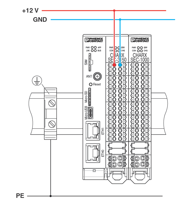
The charging controller operates with a supply voltage of +12 V DC, ±0.6 V.
You can connect multiple charging controllers using the DIN rail connector. Only one charging controller has to be supplied with power. The attached devices are supplied via the DIN rail connector.
NOTE: When controlling the load contactor from the AC power grid, make sure that the 12 V power supply and the contactor control are connected to the same phase. The power supply must be dimensioned in such a way that you can discharge the surge voltages required by standards.
Dimension the power supply for your station in accordance with the connected charging controllers and the I/O devices that are supplied by them. For the no-load current consumption of the relevant devices, refer to “Technical data” on page 141.
NOTE: Observe the maximum current carrying capacity of the backplane bus
The nominal current of the backplane bus for supplying power to the modules is 6 A.
On the system side, it is ensured that the charging connector locking mechanism cannot be controlled at the same time. Observe the current consumption of each device when configuring a CHARX control modular AC station. Please note that the current consumption of the individual devices depends on the connected I/O devices and the configuration. Determine the maximum possible current consumption of your setup.
Connecting the supply voltage
Figure 4-1Connecting the power supply
Connecting the charging interface
You can operate the charging controller in a charging station with a charging socket (charging case B in accordance with IEC 61851-1). Alternatively, the charging station can also be equipped with a permanently fastened charging cable with charging connector (charging case C). The corresponding configuration is performed in the web-based management (see “Charging Connection” on page 89).
Charging stations with charging socket
NOTE: Operation with 3-pos. locking actuators only with external protective circuit
The charging controller is optimized for operation with charging sockets with a 4-pos. locking actuator. Operation of the charging controller with charging sockets with 3-pos. locking actuators can result in the charging controller malfunctioning and becoming damaged. Provide an external protective circuit (see “Charging sockets with 3-pos. locking actuator” on page 54).
NOTE: Observe the maximum current carrying capacity of the charging socket
Make sure that the set maximum charging current does not exceed the current carrying capacity of the charging socket used (see “Energy” on page 90).
Charging sockets with 4-pos. locking actuator
Figure 4-2Connecting the charging socket with 4-pos. locking actuator
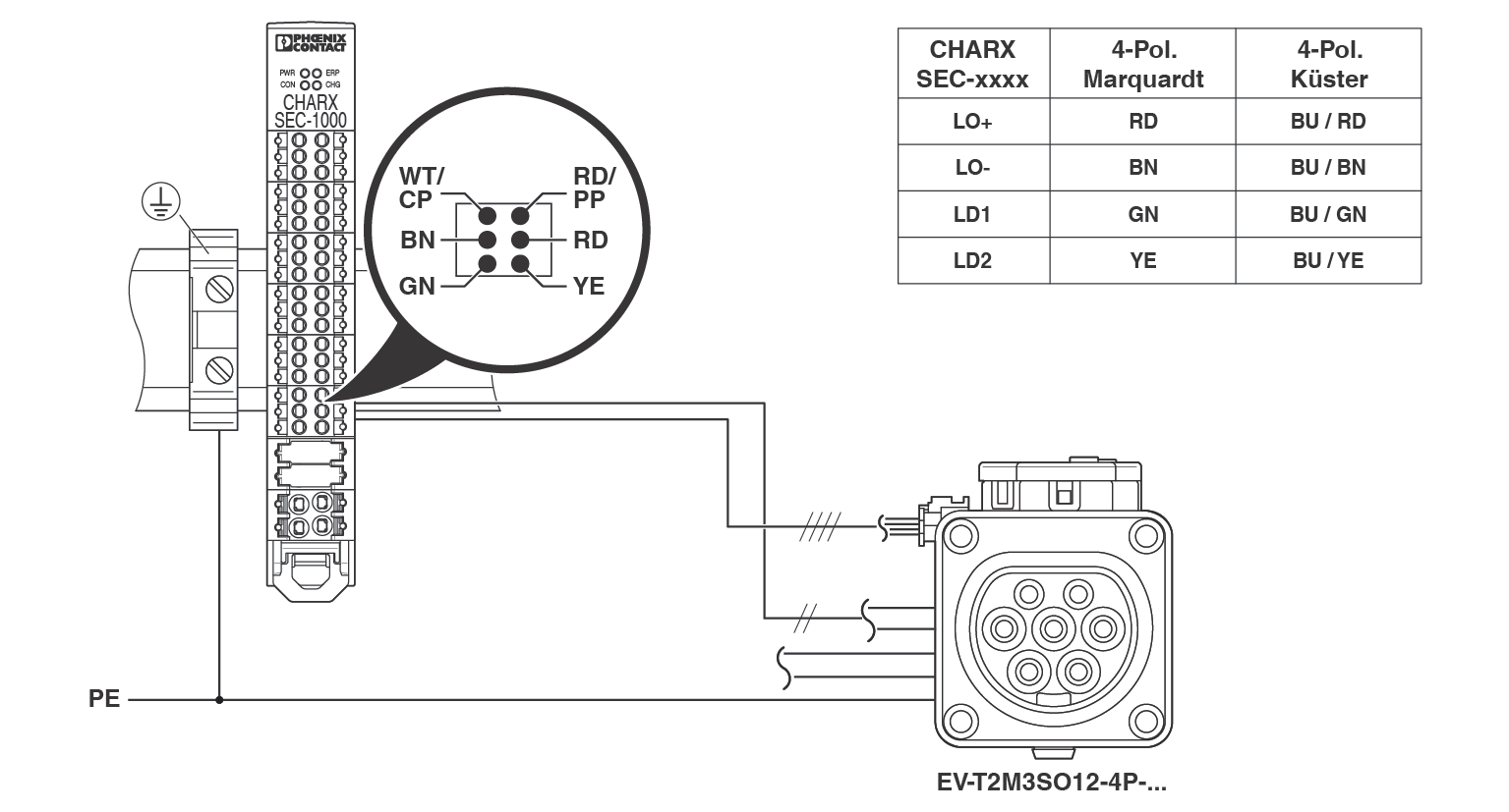
•Connect Control Pilot (CP) and Proximity (PP) to the “Socket” connector of the charging controller.
•Make sure that the protective conductor connection of the charging socket is connected to the DIN rail of the charging controller.
•Connect the locking actuator as per Figure 4-2 and the installed charging socket to the “Socket” connector.
Configuration of the control and feedback signals of the charging socket is performed in the web-based management. There, select a charging socket from Phoenix Contact (see “Charging Connection” on page 89).
•Select “Socket” as the connection type. Select the type of the charging socket used from the drop-down menu.
•The corresponding parameters for evaluation and control are set automatically.
Charging sockets with 3-pos. locking actuator
Figure 4-3Connecting the charging socket with 3-pos. locking actuator
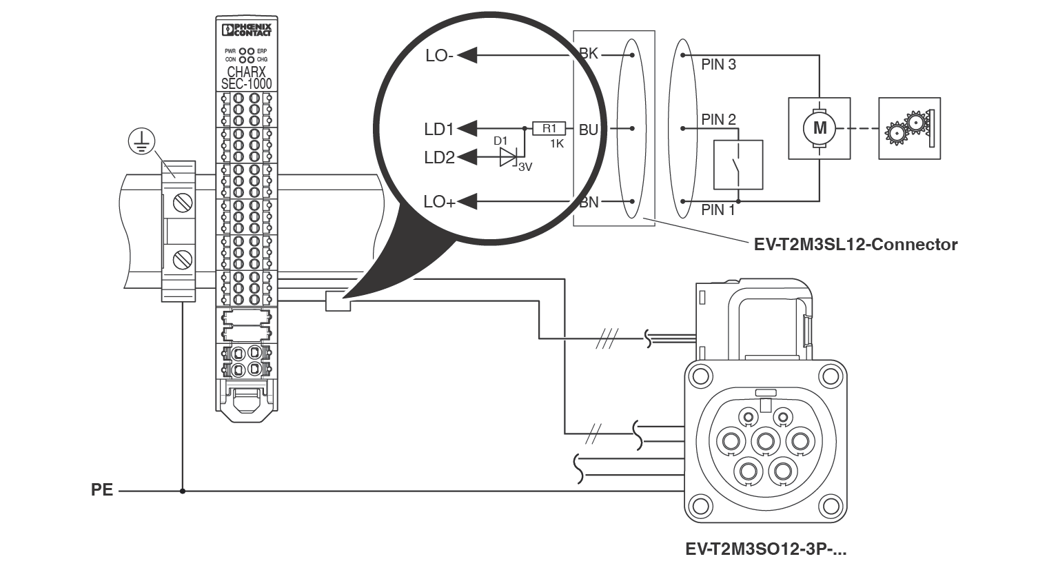
•Connect Control Pilot (CP) and Proximity (PP) to the “Socket” connector of the charging controller.
•Make sure that the protective conductor connection of the charging socket is connected to the DIN rail of the charging controller.
•Provide a protective circuit to protect the “Lock Detection” input against excessively high voltages. The protective circuit consists of a 1 kΩ resistor and a 3 V Zener diode in accordance with Figure 4-3.
Configuration of the control and feedback signals of the charging socket is performed in the web-based management. There, select a charging socket from Phoenix Contact (see “Charging Connection” on page 89).
•Select “Socket” as the connection type. Select the type of the charging socket used from the drop-down menu.
•The corresponding parameters for evaluation and control are set automatically.
Charging stations with charging connector
Figure 4-4Connecting the charging connector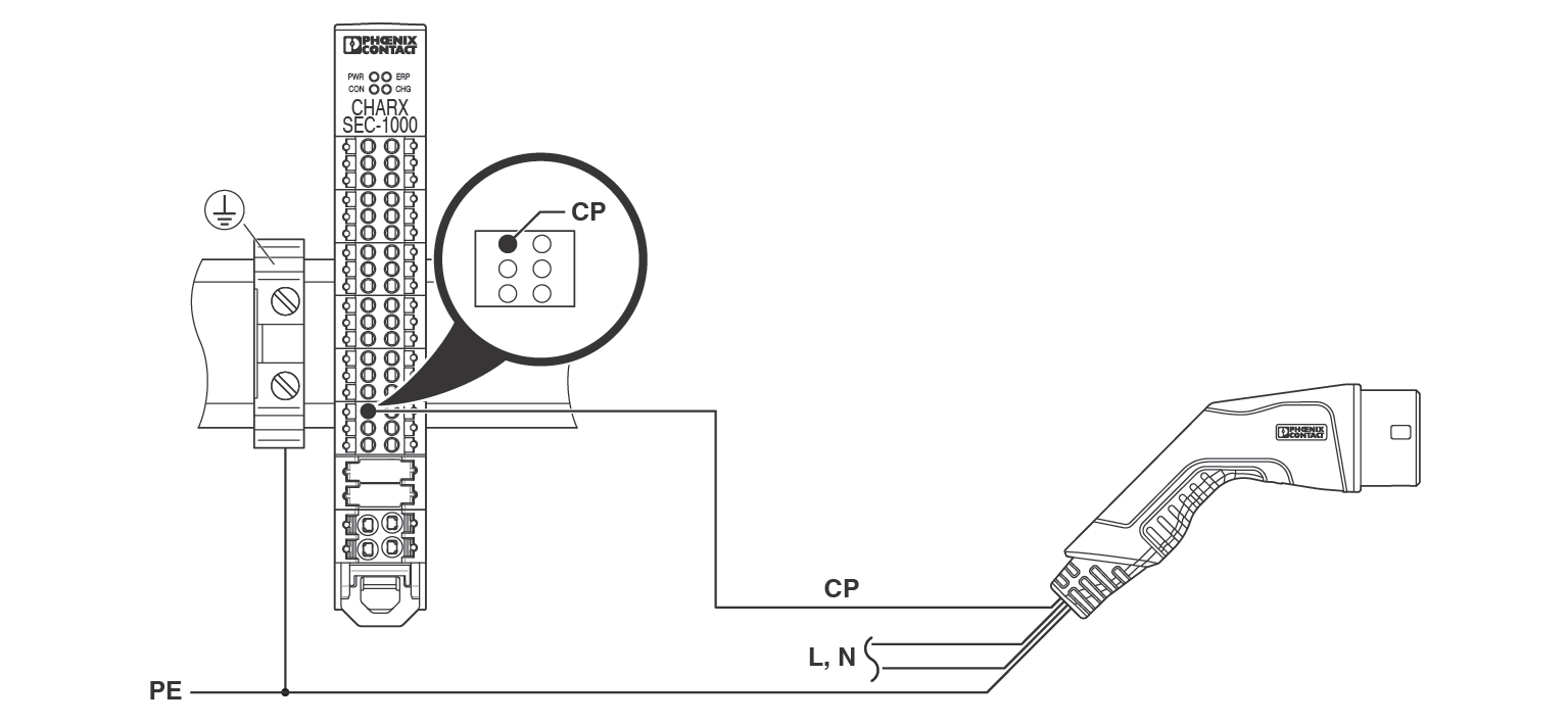
•Connect the Control Pilot (CP) of the charging connector to the “Socket” connector of the charging controller.
•Make sure that the protective conductor connection of the charging connector is connected to the DIN rail of the charging controller.
•Select “Connector” as the connection type in the web-based management (see “Charging Connection” on page 89).
NOTE: Observe the current carrying capacity of the charging connector
Make sure that the set maximum charging current does not exceed the current carrying capacity of the charging connector used (see “Energy” on page 90).
Connecting the load contactor
The load contactor connects the electric vehicle to the power grid. It is automatically switched on and off by the charging controller via a floating contact. Switching is in accordance with the normative requirements and charging releases.
Charging stations without communication with the electric vehicle in accordance with ISO/IEC 15118 (CHARX SEC-1000, CHARX SEC-3x00): In this case the load contactor is switched with a DC voltage <30 V or with a mains voltage <250 V AC.
Charging stations with communication with the electric vehicle in accordance with ISO/IEC 15118 (CHARX SEC-3x50): The mains voltage should be used for contactor control in order to detect the zero crossing of the mains voltage (zero cross detection).
Variable „NOTE“ ist nicht definiertWhen controlling the load contactor from the AC power grid, make sure that the 12 V power supply and the contactor control are connected to the same phase. The power supply must be dimensioned in such a way that you can discharge the surge voltages required by standards.
If the load contactor does not close despite charging being released, check that the residual current sensor or the bridge is wired correctly (see “Residual current monitoring” on page 59)
Load contactor for charging controllers without ISO/IEC 15118 communication
Figure 4-5Load contactor control without ISO/IEC 15118 communication
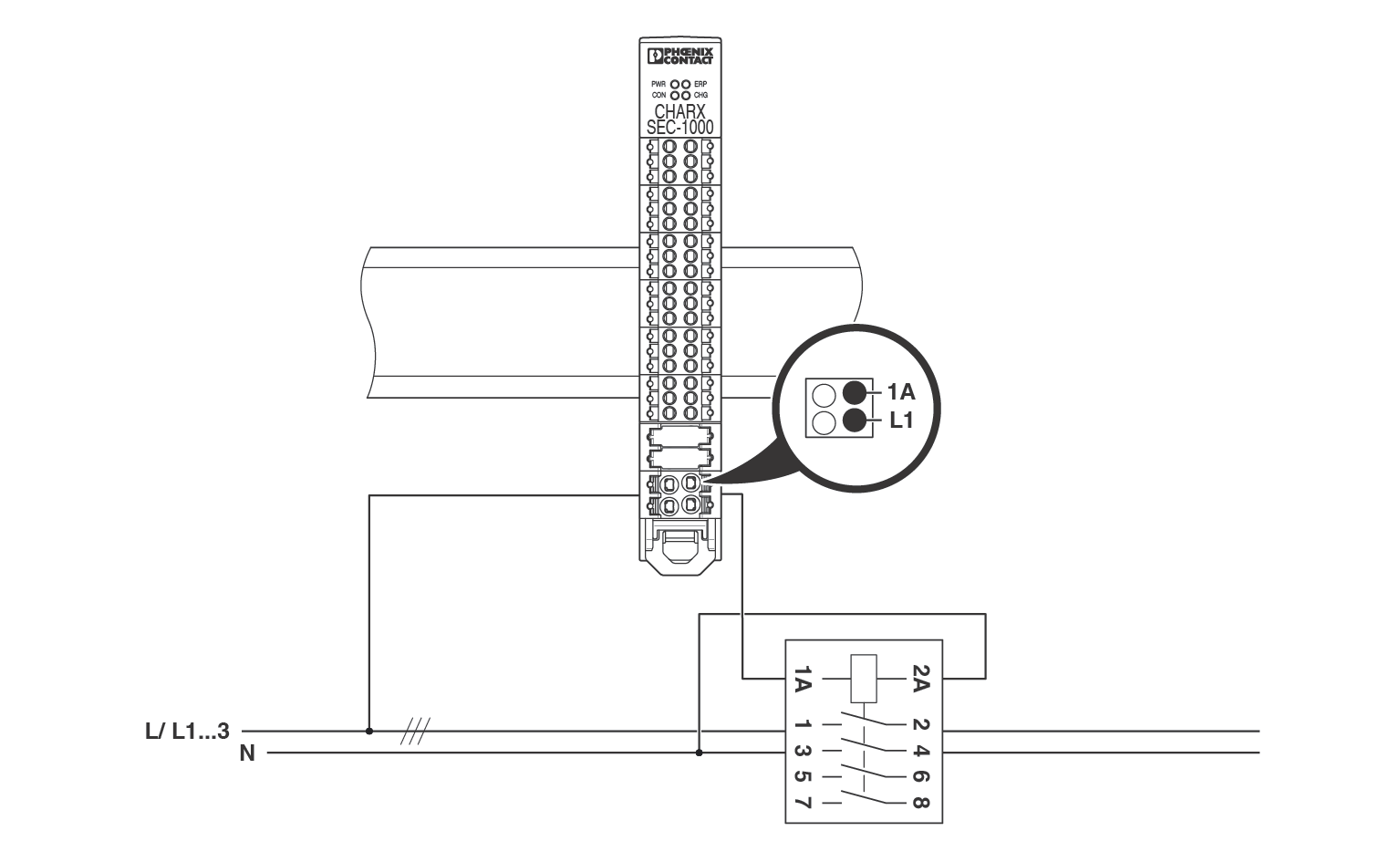
•Connect the control voltage for the load contactor to the mains voltage or a DC supply voltage.
–Input C1 (CHARX SEC-1000)
–Input C1/L1 (CHARX SEC-3xxx)
•Connect the output to control input 1A of the load contactor.
–Output C2 (CHARX SEC-1000)
–Output C2/L1* (CHARX SEC-3xxx)
•Route output 2A of the load contactor to the neutral conductor or to the GND potential of the DC power supply.
–Neutral conductor for contactor control with mains voltage
–GND potential for control with DC supply voltage
Load contactor for charging controllers with ISO/IEC 15118 communication
Figure 4-6Load contactor control with communication in accordance with ISO/IEC 151183
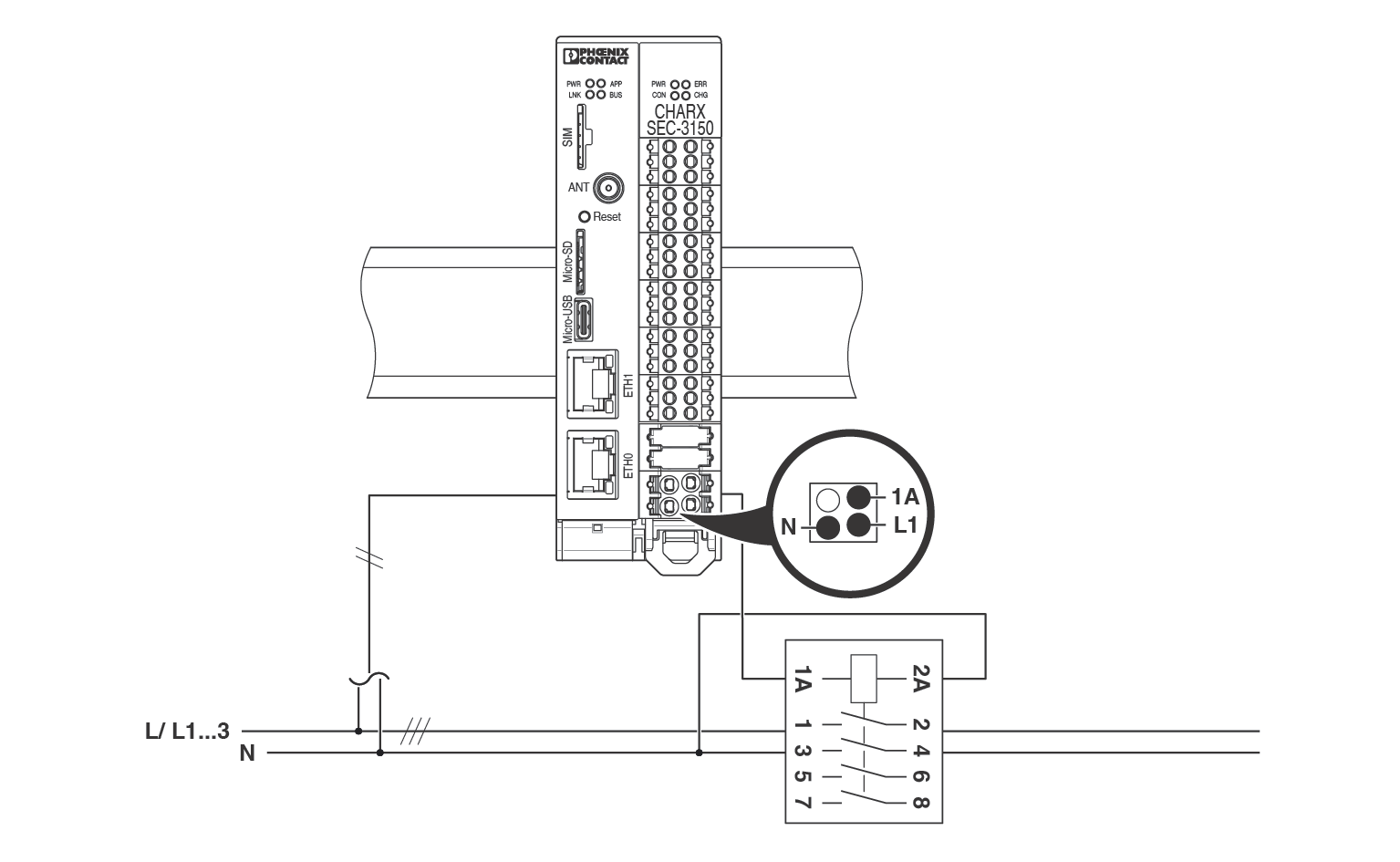
•Connect conductor L1 of the mains voltage to input C1/L1.
•Connect the neutral conductor to contact N on the “Contactor” connector.
•Connect output C2/L1* to control input 1A of the load contactor.
•Route output 2A of the load contactor to the neutral conductor.
Monitoring the load contactor for malfunction
It is possible for you to monitor the load contactor for malfunction using an auxiliary switch.
Contactor monitoring at the load contactor using an auxiliary switch
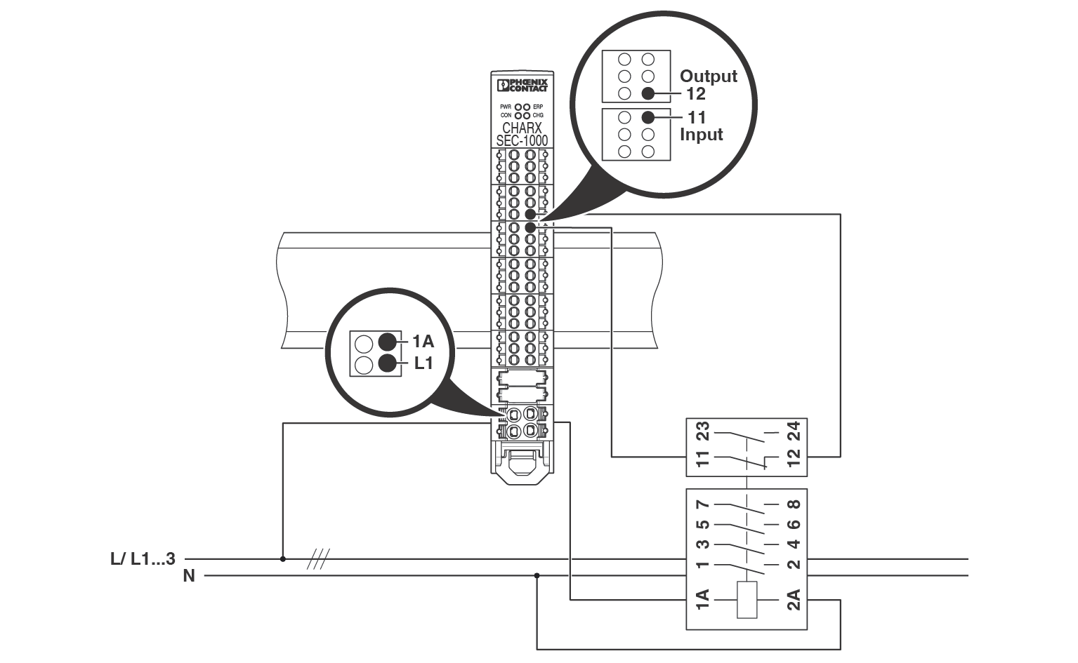
•To monitor the load contactor, connect a 12 V potential to a free digital input via the auxiliary switch.
In the web-based management of the charging controller, specify the input you use for the function. Specify whether the auxiliary contact is normally closed or normally open (see “Monitoring | Charge Current Monitoring” on page 91).
Residual current monitoring
In accordance with IEC 61851-1, DC residual currents are to be expected in charging stations for electric vehicles, which can impair the function of the residual current protection. Therefore, in accordance with the standard, one of the following measures should be implemented:
–Use of a type B residual current device
–Use of a type A residual current device. In addition, use of equipment to ensure that the power supply is safely disconnected in the event of a DC residual current greater than 6 mA.
The CHARX control modular AC charging controllers are designed to support the implementation of both of these measures.
Operation without a DC residual current sensor – with a type B residual current device
Figure 4-7Operating the charging controller with a type B all-current-sensitive residual current device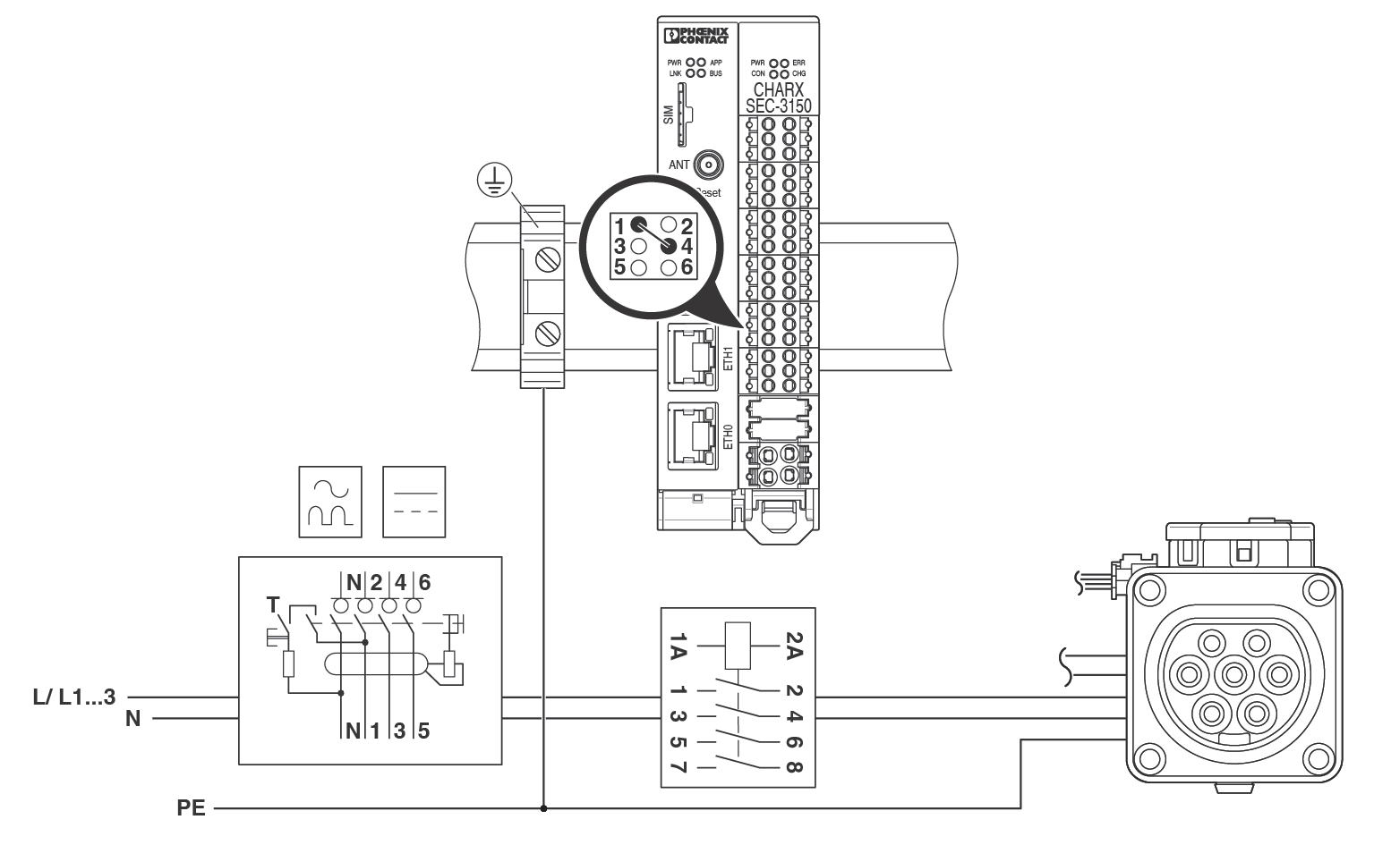
To operate the charging station with type B all-current-sensitive residual current protection, you must create a bridge between contacts 12V and ER2 on the “RCM” connector.
•Make sure that residual current monitoring is disabled in the web-based management (see “Monitoring | Charge Current Monitoring” on page 91).
Operation with a DC residual current sensor
When operating the charging controller with a 6 mA DC residual current sensor, sensors that provide either an Active High or an Active Low signal in the event of a fault can be used. The signal is provided via an open-collector or open-drain output. The charging controller has an integrated pull-up resistor to 12 V.
Contacts 12V and 0V on the “RCM” connector are available to supply power to external sensors. To test the residual current sensor, the charging controller provides a 12 V test signal at terminal point 5 of the “RCM” connector. The charging controller controls the test signal automatically.
To use the charging controller with external residual current sensors, enable the function in the web-based management of the charging controller (see “Monitoring | Charge Current Monitoring” on page 91).
Figure 4-8Operation of the charging controller with a DC residual current sensor
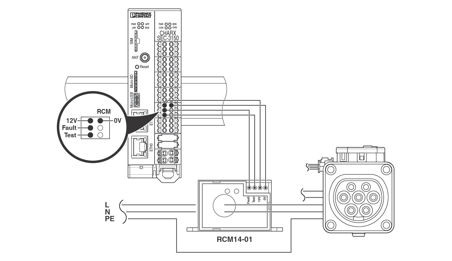
Figure 4-8 shows the operation of the charging controller with a DC residual current sensor with 12 V fault signal (e.g., Western Automation RCM14-01/RCM14-03).
•When using residual current sensors that provide an Active High or 12 V signal in the event of a fault, connect the fault output of the sensor to contact ER1 on the “RCM” connector (see Figure 4-8).
•When using residual current sensors that provide an Active Low or 0 V signal in the event of a fault, connect the fault output of the sensor to contact ER2 on the “RCM” connector. The connection between the charging controller and the RCM module is established via an XHP-4 connector from JST. An assembled cable for connecting the components is available as CHARX SEC JST-RCM-CBL, 1360462.
NOTE: Reversing the polarity of the “Fault” and “Test” contacts leads to a short circuit on the DC residual current sensor. The DC residual current sensor is then no longer functional!
Connecting the energy measuring device
Figure 4-9Connecting EEM357
In order to record charging currents, you can connect an energy measuring device. Use the RS-485 interface on the “Meter” connector for this.
The charging controller currently supports the following energy measuring devices:
–Phoenix Contact EEM-350-D-MCB, 2905849
–Phoenix Contact EEM-DM357, 1252817
–Phoenix Contact EEM-DM357-70, 1219095
–Phoenix Contact EEM-EM357, 2908588
–Phoenix Contact EEM-EM357-EE, 1311985
–Phoenix Contact EEM-EM157-EE, 1311993
–Phoenix Contact EEM-AM157-70, 1219090
–Carlo Gavazzi EM24
–Carlo Gavazzi EM111
–Carlo Gavazzi EM340
–Inepro PRO380-Mod
–Iskra WM3M4(C)
Configuration of the communication interface for the energy measuring device
In the web-based management of the charging controller, select the energy measuring device used (see “Energy” on page 90).
In order to establish a connection between the charging controller and energy measuring device, the settings for communication must correspond to the default settings of the selected device. This applies, for example, to the device address and transmission speed.
We plan to extend the list of supported energy measuring devices in future software updates. You can view the energy measuring devices implemented in your software version in the charging point configuration in the web-based management (see “Charging Stations/Charge Point/Configuration” on page 88).
Connecting the energy measuring device for certain functions
Always connect an energy measuring device if you want to use functions for current monitoring (overcurrent and out-of-balance monitoring) or load management.
Connecting an RFID reader
In order to authorize users, you can connect RFID readers via the “Supply/RFID” RS-485 interface. You can check the read RFID cards against a local white list or an external management system.
It is possible to use one RFID reader for multiple charging points.
The RFID reader can be supplied with 12 V voltage from the “Supply/RFID” connector.
•Connect the communication cables of the RFID reader to contacts A+/B- of the “Supply/RFID” connector.
Proceed as follows to configure the communication interface for the RFID reader:
•Specify the charging releases in the web-based management of the charging controller.
•Select the RFID reader used and the charging interface used to connect the RFID reader (see “Charging Stations/Charge Point/Event Actions” on page 94).
In order to establish a connection between the charging controller and RFID reader, the settings for communication must correspond to the default settings of the selected device. This applies, for example, to the device address and transmission speed.
The charging controller currently supports the following RFID readers:
–CHARX RFID/NFC
–ELATEC T4W2 PALON COMPACT LIGHT PCB (T4W2-F02B6)
–ELATEC TWN4 PALON COMPACT LIGHT Panel (T4PK-F02TR6)
–DUALI DE-950-4, DUALI DE-950-4-CXP
–Netronix UW-XEU1
The list of supported RFID readers may be extended in future software updates.
You can view the RFID readers implemented in your software version in the charging point configuration in the web-based management (see “Charging Stations/Charge Point/Configuration” on page 88).
Connecting an RFID reader from ELATEC
Figure 4-10Connecting an ELATEC T4W2-F02B6/T4PK-F02TR6
NOTE: Adapt software to ELATEC reader
Use appropriate software to operate the RFID reader from ELATEC on CHARX charging controllers. Use the “AppBlaster” program provided by the manufacturer and the “TWN4_NCx320_STD203_Standard.bix” program file for installation.
NOTE: Do not use a termination resistor
The termination resistor (DIP switch 8) must be switched off.
The software and the program file are available in the Download area for the RFID readers (1309772 and 1309687). The RFID reader can be connected to a PC via a standard micro USB cable.
The program file provided is only compatible with bootloader version 1.08 of the Elatec readers.
Figure 4-11Software update on ELATEC RFID readers
Proceed as follows to update the software:
•Start the “AppBlaster.exe” program.
•Select “Program Firmware Image”.
•Select the “TWN4_NCx320_STD203_Standard.bix” file.
•Start the download via “Program Image”.
Connecting a DUALI DE-950-4 RFID reader
Figure 4-12Connecting a DUALI DE-950-4-CXP
If the RFID reader is in the default settings, no further settings need to be made on it.
Connecting a CHARX RFID/NFC RFID reader
Figure 4-13Connecting a CHARX RFID/NFC
NOTE: Reduced wireless range
Metallic components in the direct vicinity of the RFID reader may affect the wireless range. The housing must not be made of metal. The housing must not shield the antenna of the RFID reader. The distance between the RFID reader and the housing must be as small as possible, but not less than 2 mm.
•Install the RFID reader inside the housing with screws. Alternatively, the RFID reader can be fastened on screw bosses.
•Use the connecting cable to connect the RFID reader to the charging controller. The connecting cable must not exert any mechanical strain on the RFID reader.
The RFID reader is configured via the charging controller.
Connecting digital outputs
You can operate the digital outputs in the operating modes “Low Side”, “High Side”, and “Floating”.
–With “Low Side”, the output is connected to ground potential when activated.
–With “High Side”, the output is connected to a 12 V voltage when activated.
–With “Floating”, there is no through-connection to one of the reference potentials.
NOTE: Observe the maximum current carrying capacity of the digital outputs
The digital outputs are not protected against overload. Make sure that the maximum output current is not exceeded. For the maximum current carrying capacity, refer to “Technical data” on page 141.
NOTE: Observe the maximum voltage of the digital outputs
In “Low Side” operating mode, the supply voltage of the connected loads must not exceed the maximum output voltage of the digital outputs, which is 12 V.
•Make sure that the maximum output voltage of 12 V is not exceeded.
•When power is supplied from external sources, make sure that the ground potential is connected to the ground potential of the charging controller.
Figure 4-14Control of LEDs in “High Side” operating mode
Figure 4-14 shows an example of control in “High Side” operating mode. The EV-T2SOC-P protective cover with the LED area is connected to the outputs.
Figure 4-15Control of LEDs in “Low Side” operating mode
Figure 4-15 shows an example of control in “Low Side” operating mode using a 3-color LED. The outputs are configured in the web-based management (see “Charging Stations/Charge Point/Event Actions” on page 94).
Select from a predefined list to specify under which conditions and systems states or on which events an output should be activated.
–Examples of conditions and system states: Vehicle connected, charging the vehicle, charging station in error state
–Examples of events: RFID invalid, temperature derating activated
In case of activation, the digital outputs can be configured to the following operating modes:
–Permanent 12 V (“High”)
–Permanent 0 V (“Low”)
–Flashing 12 V (“Flashing High”)
–Flashing 0 V (“Flashing Low”)
–Pulsating 0 V (“Pulsatile Low”)
–Floating (“Floating”)
For flashing output signals, it is possible to specify the operating time per pulse (PWM duty cycle).
The activation time of an output can be limited using a timer.
You can link an output to multiple conditions, system states, or events and assign a different operating mode to each of them. This enables different system states to be signaled via one output.
Connecting digital inputs
Figure 4-16Wiring of the digital inputs
You can connect the digital inputs to passive or active signal generators. The passive signal generators (switches, buttons) use the 12 V supply of the charging controller. The active signal generators have their own 12 V supply.
NOTE: Use the same GND potential.
If the digital inputs are controlled when signal generators are active, the ground potential of the signal generators must be connected to the ground potential of the charging controller.
The digital inputs are configured in the web-based management (see “Charging Stations/Charge Point/Event Actions” on page 94).
For the “Rising edge” and “Falling edge” events, you can select an action from a predefined list for the relevant input. Multiple actions can be assigned to one input signal.
You can use the digital inputs as analog threshold switches by assigning the “Digital input 1 ... 4 above/below xxx mV” condition to the action.
Connecting temperature sensors
Figure 4-17Connecting a PTC sensor
You connect the temperature sensors via the PTC terminal points on the “Input” connector.
You can use both PTC chains and Pt 1000 sensors. The configuration of this is performed in the web-based management (see “Monitoring | Derating” on page 92).
For “PTC” operating mode, specify a resistance value at which the charging process will be interrupted. Reactivation is performed with a hysteresis of 3%.
For “PT1000” operating mode, a temperature range is defined in which the charging current is derated. The respective temperatures are assigned a current value that is still permissible for derating at the relevant temperatures. When the start temperature is reached (1), the charging controller commences derating. Linear interpolation of the permissible current (A B) occurs between the two limit temperatures. When the stop temperature is reached (2), the current setting is set to 0 A. The method of operation is shown in Figure 4-18.
Figure 4-18Derating curve for temperature measurement with Pt 1000 resistor